jaguar
Nose Gear Well
Jaguar 2.0…no…3.0…no…3.1 no…Ah screw it, it’s a complete do over of the Jaguar 1.0 (again).
This Jaguar project has gone through so many iterations over the last five to six years, I’ve lost count of which version I’m working on. The previous version, where I showcased gallery photos and an article, Jaguar Masters Part 1, came to a bad end. The masters were destroyed in the fires that swept through Paradise, Calif. A good friend had them with the intent to cast copies when that terrible fire took his home and the town. His personal loss overshadows the loss of a lump of plastic so much that I hesitate to count the loss of my masters as a loss at all.
But, back to the drawing board. I surmised the entire project needed a rethink. To create the prior version, I used CNC milled foam, acrylic structural parts and 3D-printed detail parts. My tools consisted of a Form 1+ SLA printer and a modified Sherline CNC mill for fabrication, plus I mixed in a good measure of classic scratch-building techniques. The Sherline milll took the heavy lifting for the large, structural parts and it also took time, machining and setup to manufacture the raw parts. The Form 1+ had also suffered from a poor print average; thus, only one part out of two was usable. Plus, I noticed the machine required a significant cleaning every time a part failed.
CAD Model Screenshots. I’m using Fusion 360 as my primary modeling environment .
What to do?
Casting was out for a couple of reasons: one, my work space was too small to hold the required machinery to achieve the quality castings I desired and two, the construction method I chose was too slow to start over. I needed to produce models faster without casting them. Therefore, the Sherline was inadequate and the Form 1+ was unreliable. I also assessed I wouldn’t be able to upgrade my bank account either, so it was China to the rescue. For less than half the cost of my Form 1+, I acquired two 3D printers, the Cetus MK3 and the Anycubic Photon, but sadly, the printers didn’t work very well out the box. Clearly, they’re not “plug and play.” Each needed significant adjustments and modifications to produce reliable prints and accurate parts. You’ll be able to read more about my Photon experience coming soon.
Cetus3D Mk3 (left) and Anycubic Photon (right)
Finally with these two printers up and running, and using the Sherline to cut parts that suited its strength. I embarked on my end goal: use the CAD model to produce printed and machined parts and build a prototype where I could then test the feasibility of its construction.
The strategy was easy: the Cetus MkIII printed the bulk of the model, the Sherline made bulkheads, floors and flat detailed parts, and the Photon tackled the find-detail parts. As the model was in-progress and my experience grew, I continued to modify my CAD model as well.
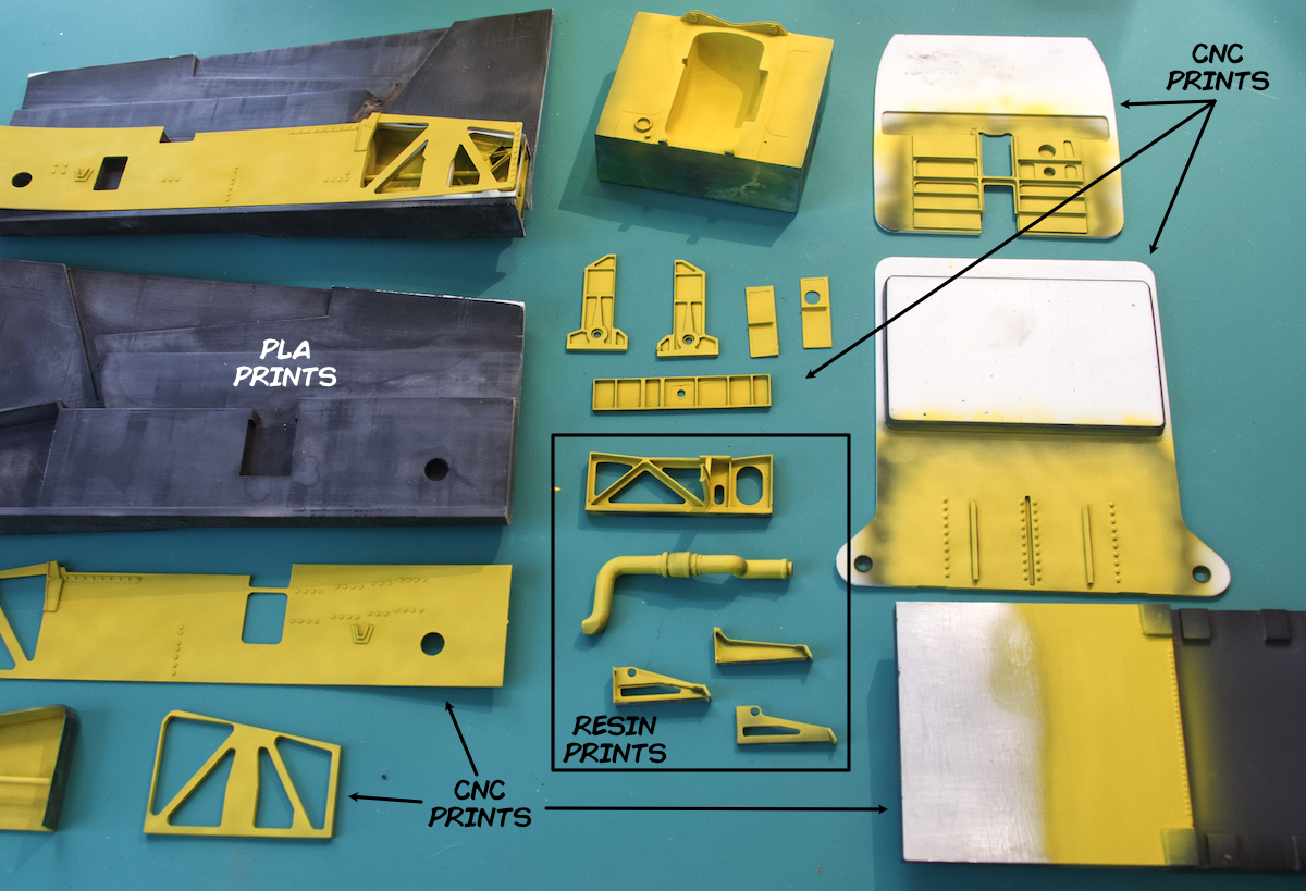
Printed and milled parts to date all in varying stages of post processing.
With that verbose recap, here are the results so far. You’ll see the completed nose gear well. Its sides were printed in PLA courtesy of the Cetus MkIII. The roof, front and rear bulkheads, were milled on the Sherline and highly detailed parts were printed on the Photon with a few exceptions. For example, the hydraulic tube brackets and the side walls veneers were constructed in styrene and the details, i.e., rivets, bolt heads, etc. were milled vice printed.
Clockwise from the bottom left corner:
Left wall details and styrene veneer with milled surface details.
Left fuselage side section
Right fuselage section with detailed part laid in place
Rear roof with blister to accommodate the nose gear wheel
Forward bulkhead
Rear bulkhead
Cockpit floor and nose gear well roof
Detail parts structural parts and fuel pipe
Small details, hydraulic line fittings, straps for the hydraulic tubing clamps and a hinge for the wheel blister.
Close ups of the initial paint and weathering
Once the parts were printed, the model assembled in a similar fashion used in constructing kits. I painted the majority of the parts before assembly. I used black Custom Shop epoxy primer, then painted a combination layer of MRP Zinc Chromate primer and Tamiya XF-4 yellow green followed by a sealer, “Future,” (Pledge Floor Care is the brand name). Finally, I added a wash of black and burnt umber oil paint. Once the base color was compete, I added in the details.
Construction sequence. The printed tubing were the first pasts installed.
I used the CAD model and generated a paper template, and I cut it to fit the area where I planned to add the detail parts. I transferred the detail location by simply drawing the outlines in pencil. You can see the extensive hydraulic plumbing that covered nearly every surface. The Photon was responsible for printing a handful of the tubes like those that are woven around the structure at the rear side of the gear well and tubing that those that required complex bends where accuracy was important. I fashioned the remaining tubing from 0.025” and 0.030” lead wire and superglued it in place. I spent a significant amount of time deciphering where each line’s start and end points, but working one line at a time, I eventually secured them to their correct locations, at least 98.78% percent of them.
Detail shots of the hydraulic tubing installation
Once the hydraulic plumbing was complete the remaining details were added along with the associated wiring.
Nose Gear Uplock
Weapon Main Unit
For the last assembly steps, I joined the halves and front and rear bulkheads, then I added the “fill” panels to close off the well and define the gear door openings.
The completed well view looking forward
Left and right sides of the well
Detail views of the right side
Detail views of the left side
Rear bulkhead
Detail shot of the filler parts
The completed nose gear well…ready to move on to the next part of the build
That’s in for now. I’m not sure what I’ll tackle next, I could use a break from fine detail so I’m leaning toward construction of larger parts and surface finishing. More soon and thanks for stopping by.
Written and performed by,
Timmy!
October 26, 2019


