Shape shifting
The Airframe Modifications
As always I have always approached model building in much the same way as an oil painter. That is, to ad layers of detail until I achieved the desired result. This installment is the the first layer of detail. With the kit instructions long since lost, it was time to figure our how to complete the assembly if the model. Since the model was mounted in an inflight pose, assembly was pretty quick. Fuselage halves, tailpipe, canopy and wings were glued up and viola the model was essentially complete, construction wise anyway.
Installing the shape templates
The drawings I prepared were the key to getting the differences nailed down between the original Hawk and the Goshawk. The gross differences were in the nose and wings. In order to allow the Goshawk to operate in the aircraft carrier environment the Navy made significant changes to the airframe. First the landing gear structures were redesigned to withstand higher sink rates to touch down and the resulting higher impact forces. Also to withstand the stress of catapult laugh operations. The biggest airframe modification was the nose area. The area was widened and deepened to fit a two wheeled nose gear assembly. The upper lines of the hawk nose were unchanged and the cockpit structure is essentially unchanged. So the addition of bigger gear meant room was added to the sides and lower portion of the nose. When viewed in profile the lower fuselage line is much deeper and flows smoothly from the tip of the nose to the wing root.
The wing was also modified to allow for lower landing speeds as well as heavier landing gear. The most obvious addition was the leading edge slats, that changed the wing leading edge profile to a straight line from root to tip. The wing tip was also squared off and there is some significant aerodynamic twist in the tip, presumably added to control the low speed stall characteristics of the wing. The landing gear was mounted further out on the wing towards the tips and bumps were added to the top of the wing near the fuselage intersection, to accept the larger gear.
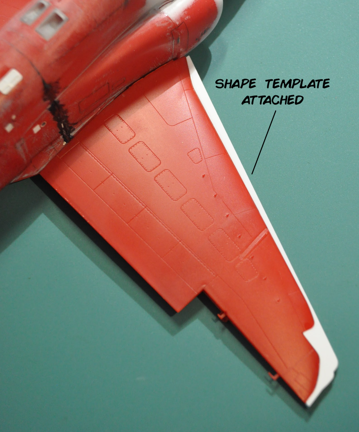
My drawings started as an depiction of the real jet. Using published data, “measurements” and photographic evidence I crafted an accurate as can be set of drawings. All the details were drawn including each rivet; yes I counted them! In order to scale the drawings to the model I placed the fuselage halves, wings and stabilators on a flatbed scanner and crated scans of the parts. The scans were imported to by drawing and the drawing was scaled to fit the parts. I then drew templates for the plastic profiles that were added to the kit parts to guide the shape modifications.
For the fuselage I cut some sheet plastic by hand and filed and sanded it to fit the kit part and match the printed plan, a time consuming process. When I got to the the wing modifications. I smartened up and used my CNC mill. Taking shapes directly from my scaled drawings I modeled the plastic templates in CAD and cut them with my mill, less time consuming and more accurate not to mention symmetrical. Achieving symmetry was always something I found difficult to do. The stabilator and vertical tail tips are also changed the stabs squared off and the vertical tail lengthened. Those templates were cut on the CNC mill as well.
Details, Details
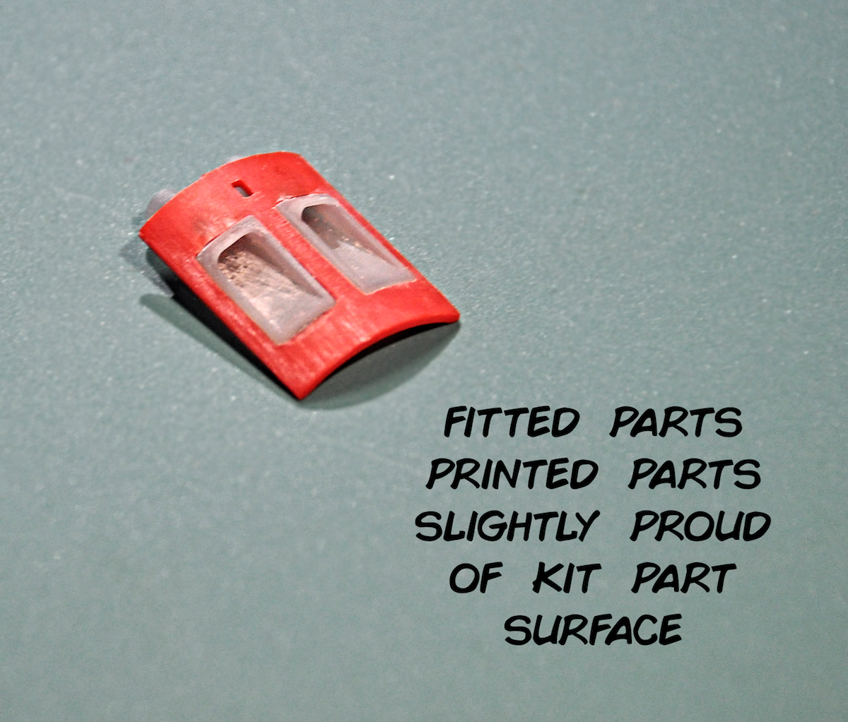
There were a handful of detailing items that needed to be addressed before I could close the fuselage. On the spine the air-conditioning system exhausts were added. These 3d printed parts were added not because the kit parts were wrong, per se, but because I wanted to have some depth to the parts so they looked like the exhaust was going into the aircraft. I didn’t want a blanking plate painted black that using the kit parts would have required. The same philosophy was applied to the gas producing starter system Gas Turbine Starter (GTS) exhaust. This GTS exhaust was also a 3d printed. Of significant note is the GTS exhaust is NOT mounted on the centerline. It is offset to the left (port) by an inch or two. (Dang McDonnell Douglas….I’ll never win an IPMS award now!)
Several CNC styrene details parts were added, three NACA ducts, one at the nose, two near each side of the forward vertical tail. Also the GTS intakes, the small louvered panels just forward of the GTS exhaust. A hole was cut onto the fuselage and carefully enlarged until I achieved a press fit of the new styrene parts. Two “windows” were added to each fuselage half for the hydraulic reservoir gauges. There were made from 0.040” acrylic sheet rectangles fit to holes in the fuselage, sanded to blend into the fuselage surface and polished back to clear. The gauges were represented by plastic discs with hand painted gauge faces. These were mounted to vertical styrene tabs glued to the inside of the fuselage. Then various holes and bits of aluminum tube were added for all the various exhausts and intakes that are present on the fuselage sides. Once any detail that required drilling or cutting into the fuselage half was added the halves were closed up and the wing glued up.
Canopy and Windscreen
The canopy and windscreen were next. My instrument panel coaming was a little too true to scale and the windscreen no longer fit. So out came the sanding tools. A little bit was removed from the coaming and a lot of material was removed from the windscreen. I started by sanding the windscreen but no, there was too much. Mr. Dremel tool was put into service and the windscreen was thinned out to fit. Then polished back to clear and dipped in “Future.” Future is the original brand name for clear acrylic floor finish, now branded as Pledge. Many many articles about this stuff can be found with a web search, I shall say no more. The canopy was also sanded and polished, not to make anything fit but to smooth the surface and increase the clarity. Internal details were added, the canopy fracturing system’s mild detonation cord (MDC) and canopy bow. These details were created by applying tape to the inside of the canopy and drawing out the shapes of the details. Then tape was removed and placed on a flat sheet of plastic, careful to align the drawings and witness marks. The plastic sheet with the tape patterns was placed on my flat bed scanner and imported the images to my drawing program. The details were redrawn digitally and cut with a Silhouette vinyl cutter. The vinyl was added to the canopy then dipped in Future. The inside of the canopy was then painted, white then black each layer offset by a small amount to represent the caulking and internal structure of the canopy frame.
Finishing the Shape
Turning back to the airframe modifications, the Bondo auto body glazing and spot filler was applied to the model over the shape templates. Sanding and filing the profiles first until the white plastic template material was revealed. It was a matter of standing the putty to match the 3d shape. On the nose I used a additional template to get the plan view profile in shape.
That’s it for this installment. The next layer of surface details is next and prepping the model for a coat of paint.
Up Next....
Lots and lots of bumps
Written and performed by,
Timmy!
June 26, 2018


